mkdir cadence
cd cadence
icds &
2.
Library Creation
Next open the Library
Manager window open:
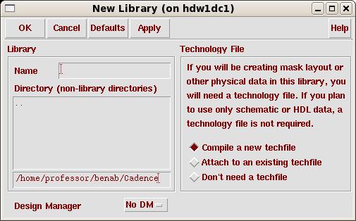
Now we need to create a new library (to
contain your circuits)
so go to File -> New -> Library from the File menu of
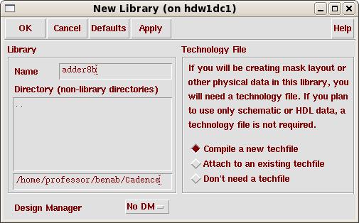
the Library Manager. Then fill in the name of the new library
(e.g. adder8b) in the dialog window, and leave the Path
empty (this will create the library in the directory where
you started icfb.
Now the lab8b library should appear in the Library Manager window. Let's start our first schematic now!
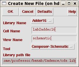
You should get the lab2adder16
Schematic Editing window.
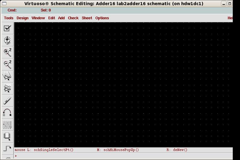
Spend some
time analyzing the window. On the left side you have various
shortcuts to common used commands such as: placing component
instances (looks like an IC), drawing wires, placing ports,
stretching, copying, zooming in and out, saving, etc. If you pass
the mouse pointer on top of the buttons you get short pop-up
help messages. You also
have access to these commands (and others) from the menu.
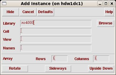
Click on the Instance button (or go to
Add -> Instance), this will pop-up
two small windows, one being a Component Browser window.
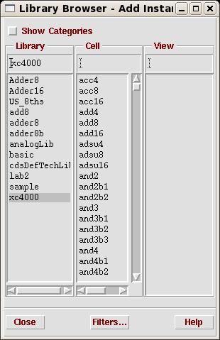
In this window choose xc4000 as the library.
Clicking Browse you will get the
following window.
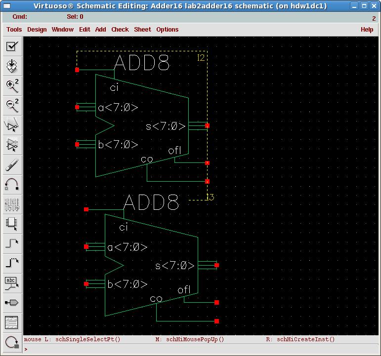
then add all your components.
the following are some keyboard shortcuts for commonly used commands.
Assuming there are no errors
we are now ready to start simulation!
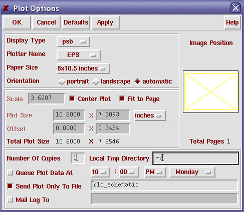
For all of your labs, you will need to turnin printouts of the designs you created. In order to print your schematic, use the following procedure.
Select Design => Plot => Submit. You will be presented with the Submit Plot window as shown here.
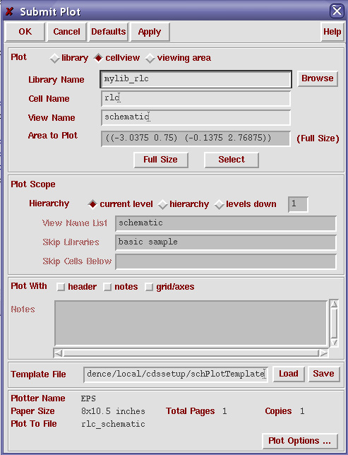
2. Click on Plot Options... in the lower right hand corner of the window. You will be presented with the Plot Options window as shown here.