- Circuit design: Design of circuit logic that allows electronic components to perform a specific function.
- Combinational logic design: The design and implementation of logic functions whose outputs depend solely on their inputs. The full adder introduced in F5 is just such a circuit.
- Sequqntial logic:
Sequential logic output depends on stored levels and also the input
levels.
- Bolean algebra: In boolean algebra, there are three basic logic operations: OR, AND and NOT. These logic gates are digital circuits constructed from diodes, transistors, and resistors connected in such a way that the circuit output is the result of a basic logic operation (OR, AND, NOT) performed on the inputs.
- Truth Table: A truth table is a means for describing how a logic circuit's output depends on the logic levels present at the circuit's inputs. In the following two-inputs logic circuit, the table lists all possible combinations of logic levels present at inputs A and B along with the corresponding output level X.
When
either input A OR B is 1, the output X is 1. Therefore the "?" in the
box is an OR gate.
- Describing Logic Circuits Algebraically: Any logic circuit may be completely described using the Boolean operations, because the OR gate, AND gate, and NOT circuit are the basic building blocks of digital systems.
- Boolean Theorems :
| (9) | x + y = y + x (commutative law) |
| (10) | x * y = y * x (commutative law) |
| (11) | x+ (y+z) = (x+y) +z = x+y+z (associative law) |
| (12) | x (yz) = (xy) z = xyz (associative law) |
| (13a) | x (y+z) = xy + xz |
| (13b) | (w+x)(y+z) = wy + xy + wz + xz |
| (14) | x + xy = x |
| (15) | x + x'y = x + y |
- minterm: A minterm is a Boolean expression resulting in 1 for the output of a single cell, and 0s for all other cells in a Karnaugh map, or truth table. If a minterm has a single 1 and the remaining cells as 0s, it would appear to cover a minimum area of 1s.
- maxterm: A maxterm is a Boolean expression resulting in a 0 for the output of a single cell expression, and 1s for all other cells in the Karnaugh map, or truth table
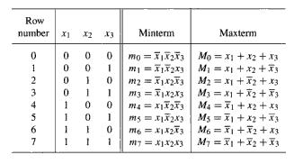
Example of mintrem and maxtrem
- Literal: each appearance of a variable or its complement in an expression
3 variables, 10 literals
Hazard
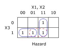
This Karnaugh Map shows the circuit. The two gates are shown by solid rings, and the hazard can be seen under the dashed ring. The theory proved by Huffman tells us that by adding a redundant loop 'X2X3' this will elimate the hazard. So the resulting logic is of the form shown in the next figure.
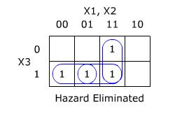
So our original function is now: f =X1.X2 + X1'.X3 + X2.X3
Now we can see that even with imperfect logic elements, our example will not show signs of hazards when X1 changes state.
- A hazard in digital logic is a fault in the logic system due to a change at the input.
- Definition: "When one input variable changes, the output changes momentarily when it shouldn't"
- A static hazard
is when the output of a logic circuit momentarily changes when its
final value is the same as its value before the hazard (when the output
is "trying" to remain the same, it jumps once, then settles down). For
example, output going from 0 to 1 to 0 (it's "trying" to stay at zero
but failing once - thus the hazard).
- A dynamic hazard is where a logic circuit will momentarily change back to its original value while changing to a new value. For example, output going from 0 to 1 to 0 and finally to 1 (it's "trying" to go from simply 0 to 1).
- There are two types of static hazards: a low-going glitch
(or static one
hazard) is where the high output transitions to a low and back high
(1-0-1) and a high-going glitch (or static zero hazard
) is where the low output transitions to a high and back low (0-1-0).
- Static 0 hazards occur in product-of-sums implementations, but do not occur in sum-of-products implementations. Static 1 hazards occur in sum-of-products implementations, but do not occur in product-of-sums implementations
Let us consider an imperfect circuit that suffers from a delay in
the physical logic elements i.e. AND gates etc.
The simple circuit performs the function:
f = X1.X2 + X1'.X3
and the logic diagram can be shown as follows:
If we first look at the starting diagram, it is clear that if no
delays were to occur, then the circuit would function normally. However
since this isnt a perfect circuit, and an error occurs when the input
changes from 111 to 011. i.e. When X1 changes state.
Now we know roughly how the hazard is occuring, for a clearer picture
and the solution on how to solve this problem, we look to the Karnaugh
Map:
This Karnaugh Map shows the circuit. The two gates are shown by solid rings, and the hazard can be seen under the dashed ring. The theory proved by Huffman tells us that by adding a redundant loop 'X2X3' this will elimate the hazard. So the resulting logic is of the form shown in the next figure.
So our original function is now: f =X1.X2 + X1'.X3 + X2.X3
Now we can see that even with imperfect logic elements, our example will not show signs of hazards when X1 changes state.
- Combinational Circuit: A combinational
circuit is one for which theoutput value is
determined solely by the values of the inputs.
- Seqential Circuit: A control system determines its outputs depending on its inputs. If the present input values are sufficient to determine the outputs the system is a combinational system, and does not need the concept of state. If the control system needs some additional information about the sequence of input changes to determine the outputs the system is a sequential system. The logical part of the system responsible for the system behaviour is called a state machine.
- Finite state Machine (FSM): A finite state machine (FSM) or finite state automaton or simply a state machine, is a model of behavior composed of a finite number of states, transitions between those states, and actions. A finite state machine is an abstract model of a machine with a primitive internal memory [Wiki].
- Mealy Machines: A mealy machine is a
machine whose output is a function of the current state of memory and
the current input
-
Moore Machines: A moore machine is a machine whose output is a function of the current state of memory
Clock Signals,
Cycle Time and Frequency
- Cycle: This refers to a single complete traversal of the signal, from the rising edge, through the time when the value of the clock is one, through the falling edge, the time that the value is zero, until the start of the next rising edge. (You can actually "chop" the signal wherever you want and have it be a single cycle, as long as you only cover one cycle without "overlapping").
- Cycle Time: The amount of time required for the signal to traverse one complete cycle. For fast PC circuits, cycle time is often specified in ns (nanoseconds, or billionths of a second). Sometimes also called cycle length or similar names.
- Rise Time and Fall Time: In theory, the transition from a one to a zero or vice-versa is instantaneous. In practice, nothing is instantaneous, and the rise time and fall time measure how long it takes for the level to change from zero to one, or one to zero, respectively.
- Clock Frequency: This is also sometimes called the clock
rate or clock speed. It is simply the reciprocal of the
cycle time, and is therefore the number of cycles that occur each
second (as opposed to the number of seconds per cycle). It is usually
measured in MHz or GHz, where "Hz" is the abbreviation for Hertz,
the standard SI unit for measuring frequency. One Hertz is one cycle
per second. So for example, if a clock's cycle time is 1.25 ns, its
frequency is 1/(0.00000000125) = 800,000,000 Hertz, or 800 MHz
[PCguide].
Last update: Jan. 2009, by A.B.A